Multi-bands Digital Frequency Shift Repeaters
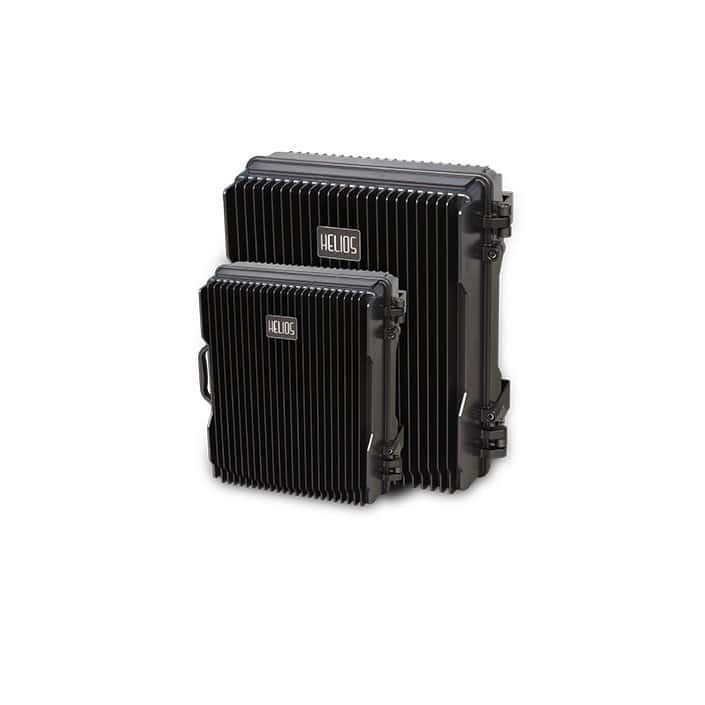
HELIOS®Digital frequency Shifting Repeaters (FSR) system designed to solve problems of weak mobile signal, which can expand more coverage than RF repeaters and reduce investment for the areas where fiber optic or dedicated cable is not allowed. The Frequency Shifting Repeater system (FSR) consists of two parts: Donor Unit and Remote Unit. The Donor Unit receives the BTS signal via open air radio frequency (RF) transmission or direct couple closed to BTS, then coverts it from the working channel to transmission channel, and transmits the amplified signal to the Remote unit that will reconvert the signal to the working channel and provide signal to the areas where network coverage is inadequate.
As per the method of receiving BTS signal by the Donor Unit, two types of FSR are available:
- Cable-Access FSR: to receive BTS signal via a direct coupler closed to the BTS (Recommended)
- Wireless-Access FSR: to receive BTS signal via a Donor Antenna (applicable when no line of sight can be viewed between the Donor Unit and Remote Unit as the Donor Unit is installed on the BTS tower)
FEATURE
- Dual Band system support for 1800MHz and 2100MHz
- Aluminum-alloy casing with lP65 protection
- Compact design, cool system without fan
- Best solution to eliminate mutual interference due to sharing the same frequency
- ALC and AGC to ensure stable operation
- Easy to install on wall or pole
- Channel and band selective automatic gain/power control for multi-operator
- Max transmission distance between Donor Unit and Remote Unit is 20KM
- Adopting filter with highly selectivity and low insertion loss eliminates interference between uplink and downlink
- Built-in RJ45 ports for local test
- Built-in 2G or 3G modem (Option) for remote monitoring by SMS, GPRS or TCP/IP
- Support upgrading firmware remotely by GPRS
- Eliminate isolation requirement in antenna installation
- Easy to choose installation site
- Integrated GPS disciplined clock provide an accurate, high-quality, stable synchronizing signal which can keep the frequency offset less than 0.01ppm all the time.
SPECIFICATIONS
Electrical Specification
Working Frequency: Uplink 1710-1785MHzMHz/1920-1980MHz; Downlink 1805-1880MHz/ 2110-2170MHz
Link Frequency: Uplink Customized; Downlink Customized
Configurable Channels: 1 sub-bands(0.6-20MHz tunable)
Frequency Error: Max 0.01ppm
GPS Calibration: Support
Output PowerPer Band: -10/23dBm(Donor); 23/40dBm(Remote)
Gain: 40/45dB(Donor); 100/100dB(Remote)
AGC Control Range: Min 40dB (±2dB)
Gain Control Range: 30dB (1dB Step)
VSWR: <1.5
Ripple in band: Max ±1.5dB
In-band Inter Modulation Attenuation: Complies with ETSI
Spurious Emissions: 9KHz-1GHz Max -36dBm; 1GHz-12.75GHz Max -30dBm
I/O Impedance: 50 ohm
Noise Figure: Max 6dB
Group Time Delay: Max 8µS
MTBF: Min. 100000 hrs
Power Supply: AC220V (+/-15%), 50Hz
Power Consumption: Donor: Max 100W
Remote: Max 300W
NMS Monitor Function: Real-time alarm for Temperature, Input Over Power, Output Power, Gain, Uplink ATT, Downlink ATT and etc.
External and Antenna Connection
RF Connector: N-type Female
Interface: RJ-45 Port
Mechanical Specification
Temperature Range: -25 degree Celsius to +55 degree Celsius
Relative Humidity: Max 95%
Dimensions: Donor 355*295*162mm; Remote 499*399*255mm
Weight: Donor 18kg; Remote 35kg


