TETRA/P25/DMR/PMR Digital CPRI Optical Transport System – Optical Remote Units (ORUs)
HELIOS® Critical Communication Digital CPRI Optical Transport System is designed to extend the coverage of Public Safety Radio TETRA, DMR, PMR and P25 into large Public Venues, such as long Tunnels sections and large area outdoor and indoor coverage.
Utilizing a centralized digital CPRI distributed architecture, HELIOS® TETRA Band Digital CPRI Optical Transport System is a two-tier architecture consisting of the Optical Master Units (OMUs) and Optical Remote Units (ORUs). RF signals from Base Stations, off-air, BDAs or combination thereof can be received. In the case of off-air feed, the OMU has the option to combine the functions of the off-air Repeater and OMU to provide transmission and distribution of radio signals. The signal is filtered and then converted to a digital CPRI data stream. The digital CPRI packet data stream is transported via single mode fiber and received by the ORUs. The ORUs then convert the digital CPRI packet data stream back to RF and amplify the signal for delivery to the antennas. On the reverse path (uplink), the ORUs and OMU perform the inverse functions and delivery the signals back to the corresponding off-air antenna, BDAs or Base Stations.
The whole system network topologies including star, chain and hybrid to cater to different deployment scenarios. These network topologies provide reduced fiber plant usage and installation cost, and effective fiber loop redundancy configurations.
Time slot Based AGC function reduces the near-far effect. When a strong signal from portable radio which uses the first time slot near the repeater causes the AGC and it reduces the uplink gain, further away portable radio which uses the second time slot in the same channel will also be affected, due to the gain reduced. With Helios® time slot based AGC function, it equalizes the signal levels between the two time slots calls, fewer dropped calls and higher reliable communication will be achieved.
Optical Master Unit - OMU
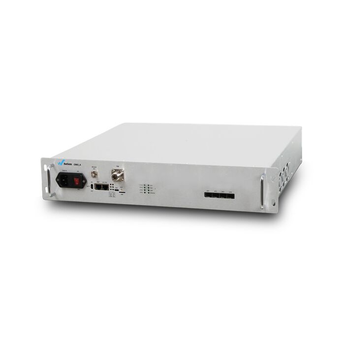
The 19” rack-mountable OMU is typically located at a Base Station. On the forward path, the OMU receives the RF signals from the BTS and digitizes the designated RF bands and digitally transports them over single mode fiber to the Remote Units. On the reverse path, the OMU receives the digitized RF signals from the Remote Unit and converts them back to RF for the BTS.
Each OMU has four 10Gbps SFP+ digital optic ports and supports up to 32 ORUs by star, chain, ring and hybrid network topologies. The OMU utilizes an embedded WEB management system for system configuration and network monitoring. The embedded WEB management system collects alarm information from both OMUs and ORUs.
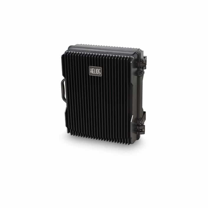
Optical Remote Unit - ORU
Typical mounting options for the ORU include pole-mount, wall-mount. And the enclosure of the ORU is fully sealed IP-67 rated compact design, which minimizes maintenance and is ideal for harsh environments.
On the forward path, the ORU receives the digitized spectrum from the OMU and converts the spectrum back into RF to be distributed via an externally mounted antenna system. On the reverse path, the ORU digitizes the designated RF spectrum and digitally transport it over single-mode fiber to the OMU.
FEATURE
- ALL Digital Software and Hardware Platform
- CPRI Transport between OMU’s and ORU’s
- Supports 4 Digital Optical Output Ports for each OMU
- Supports up to 8 Remote Units cascading in each optical port
- One OMU support up to 32 Remote Units connection
- Single Fiber core to transport
- Supports up to 10 Gb/s Digital Optical Fiber Speed
- Loop redundancy support
- Option embedded optical bypass module for non-loop redundancy architecture
- Time slot AGC and squelch support
- Long transport distance and accurate delay calibration
- RF composite DL output power +37dBm and +40dBm option
- IP67 and wall mount or pole mount of ORU
- 19” standard Rack case design of OMU
- RJ-45 Port in OMU Unit to support Local Control and Alarming via web browser GUI
- Additional RJ-45 Port for external ethernet and wireless modem
SPECIFICATIONS
Electrical Specification
Frequency Range (Customized): UL:380-385MHz /DL:390-395MHz
Technology: TETRA
Downlink Composite Output Power: 37±2dBm or 40±2dBm
Gain: Max. 45dB
Gain Adjustment: 30dB in 1 dB steps
Max Input Power without Damage: UL: ≤-10dBm
Group Delay: <14µs (1 Master and 1 Remote exclude the optical fiber delay)
Uplink Noise Figure @ Max Gain: ≤ 6dB (1 Master and 1 Remote)
IMD 3: -60dBc or -36dBm
Spurious: ≤-36dBm@9KHz~1GHz; ≤-30dBm@1GHz~12.75GHz
VSWR: <1.5
Alarm Detection: PA Fault alarm, Optical Transceiver Link alarm, Downlink output over power alarm, Door open alarm and etc.
I/O Impedance: 50 ohm
MTBF: 80,000 Hours
Power Supply: 220V AC 50~60Hz
Power Consumption: Max. 200W
External and Connection
Local Alarm Indications: LED alarm display
RF Connector: 1 * N-Type Female
Optical Connector: 2 * LC
Mechanical Specification
IP Rating: IP67
Temperature Range: -25℃ to +55℃
Relative Humidity: Max 95%
Dimension: 499*399*225mm
Weight: Max 34kg


